Wednesday, March 11, 2015

Underbody Aero Part 5 (of 5?)

It was time for the final piece of the underbody aerodynamics puzzle, the diffuser.  I started with the sheet of aluminum above, and quickly got it halfway mounted with four big chassis bolts, as you can see below.
Notice the tow hook.

I did some initial trimming to clear the  exhaust then curved it up to get an idea what the diffuser would look like.

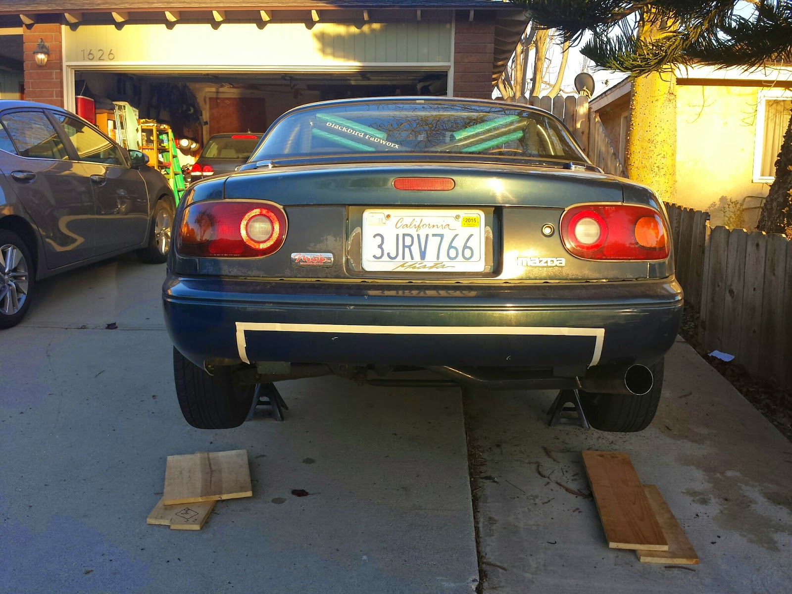
I then realized I needed to back up and figure out how wide I wanted to make the diffuser.  The aluminum was a full four feet wide, but it would definitely need to be narrowed to clear the suspension and exhaust.  The big question was if I wanted to keep the factory tie down/tow points, giving me a narrower diffuser or hack them off and go for the widest diffuser possible.  I used some tape to try to get an idea what both options would look like.
Narrow Diffuser
Wide Diffuser

I decided to go wide.  If I'm going to do it, I might as well do it to the max, plus removing the tie downs would get rid of some serious steel parts, saving a decent amount of weight.  The main drawback was that I would lose my tow hook, but I can fairly easily replace it somehow.  It would also be a decent amount more work.
The first step was removing the finish panel, which requires the removal of the license plate and tail lights.  I managed to get by with only loosening them.

Next the bumper cover came off, despite the protest of the plastic fasteners.

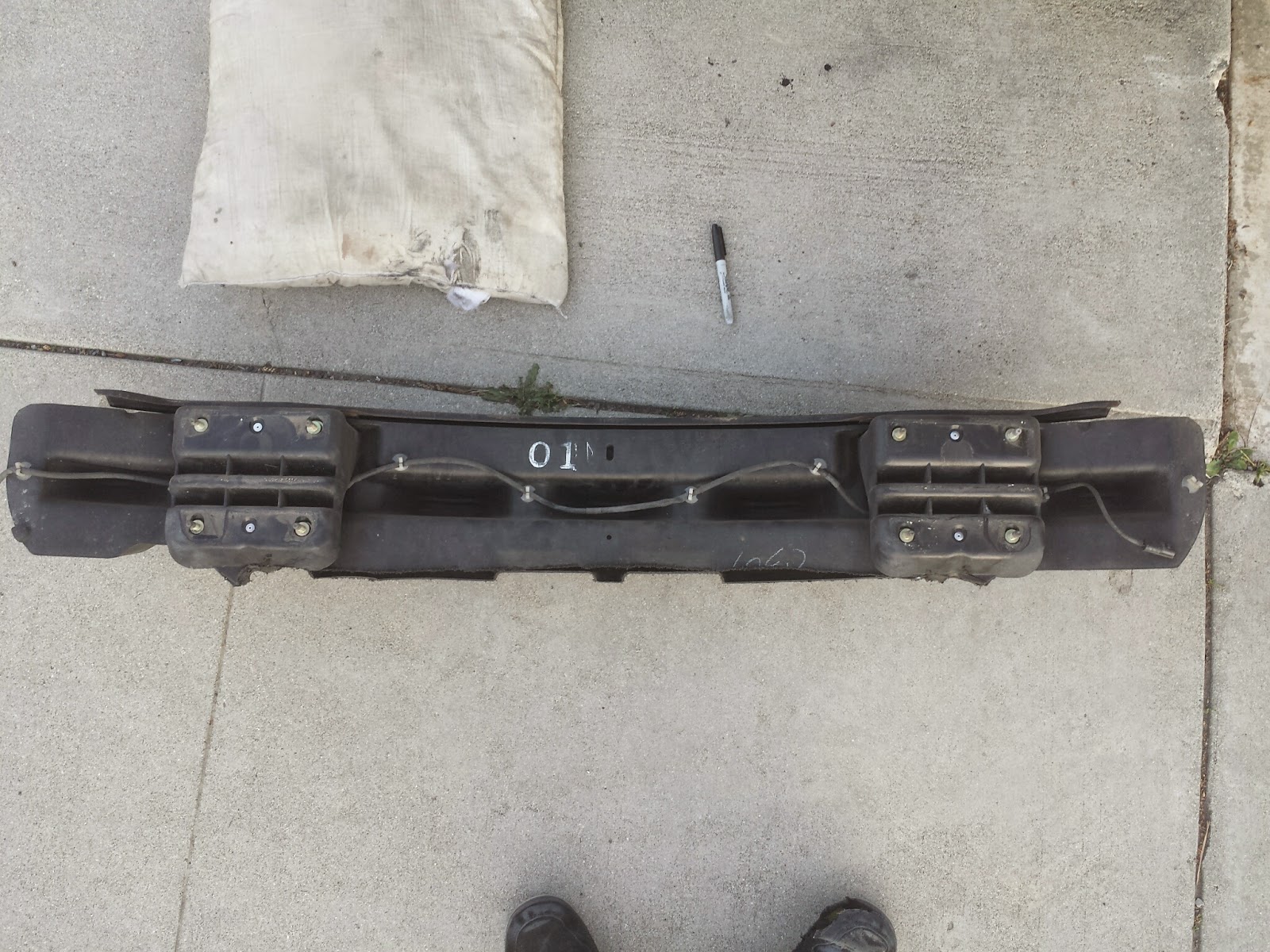
Then the plastic bumper structure came off, exposing the sections to be removed.
Rear Frame--Before
Here's everything I had to unbolt.

I heard the primary purpose of these tie downs is to secure the cars while on the ship from Japan.

I used my angle grinder to do most of the work, and I only had one incident.  The grinder caught on something and flung out of my hands.  The disk then wrapped up the pillow I was using as a knee pad and stalled.  I quickly jumped up and unplugged it.  I was actually impressed with my fast reaction and resolution.  The damage to the disk was pretty impressive.  With the installation of a new disk, I was back to work.

I eventually got the parts off, but it was a challenge.  The angles were awkward, resulting in some pretty rough looking cuts.  Fortunately, nobody will see them and judge me.

I was originally going to make the entire edge flat, but at the last minute I had the clever idea to leave the outside lower bumper mounting hole.  I would still be able to make the diffuser quite wide, and the bumper would be much more secure with it in place.  It would also turn out to be a handy mounting point later.

To avoid rust, I hit all the bare edges with some primer.

Here's what the rear end looked like when I was done making sparks.
Rear Frame--After

Now that the metal was out of the way, it was time to trim the plastic.  The reciprocating saw went though this stuff like butter.
Rear Bumper Structure--Before
Rear Bumper Structure--After
While the license plate was off, I noticed the frame was really heavy.  On the back it indicated it was solid brass.  It would have to go.  The back of the car already says Miata, so it won't be missed.

However, I'm not a big fan of bare license plates, so I used an old trick of mine and made a faux frame out of electrical tape.  Super light and decent looking.

I put the back of the car together again and got back to the aluminum.  I trimmed the front edge to match the back of the sheet in front of it and made the back as wide as would fit inside the exhaust.  It lightly touches the passenger side suspension arm at full droop, but I think it will be fine.

I discovered one of the exhaust hangers was an issue, so I decided to modify it.  The lowest portion was below the weld, so it wasn't doing anything.
Exhaust Before
Exhaust After

With the exhaust ground down, I started trimming the bumper skin.

I knew I needed to include a way for the air from my NACA ducts to escape, and I originally planned to just leave a gap between the diffuser and the bumper, but I realized that would not look very clean, so I came up with the idea to add another sheet of aluminum.  This would clean up the look (Dare I say double diffuser?) and clean up the airflow.
This is what the sheet looked like.

Here it is untrimmed and halfway installed.

This shows the final mounting.   Two of the forward bolts go into existing threaded inserts.  The other is a self drilling screw into the frame rail.  The five rearward screws go into the plastic bumper structure.


As you can see, it sits quite nicely.

With the upper part done, I started on the lower sheet again.  After much consideration on the rearmost mounting, I got a 1/8th by 1 inch strip of aluminum and bent it to attach the to bumper mounting bolts I cleverly left behind. The bending was not easy, and is by no means perfect.  I attached it to the sheet with five screws.

Once bolted up, I pretty much had the final curve to the diffuser.  I messed up a little and didn't ensure the left and right sides had symmetrical curves.  The exhaust impacted the right side.  This isn't too big an issue, except I planned to use the same shape on all the fins.
It looks fine here, but definitely needs some trimming.

I moved into the garage to get a more level surface for fin creation.  I also did the initial trimming.

I created the fin template out of cardboard based on the exhaust side, then made aluminum versions.  I started with the bottom of the fins parallel to the ground, but it looked pretty silly, so I ended up trimming three inches off the back end.

Once all the fins were made I attached them to the sheet with a whole bunch of hardware.  I might rivet it all together at some point, but I want to be able to disassemble it for now.

One more thing I needed was a piece to tie the upper sheet into the lower sheet, so I bent up one of these for each side.  They match the cut in the bumper precisely.

After all that work, here's the final result.  I had to muscle it into place due to the issue with the unsymmetrical curves, but it bolted up.  It's not perfect, but I'm still proud of it.  I think I can improve it with some tweaking, but I'm going to live with it as-is for a while. 

I definitely added some weight with all the aluminum, but I did remove some as well:
Tow Blocks:  4 lbs.
Black Bumper:  1 lb, 7 oz.
License Plate Frame:  12 oz.
Jack:  3 lb, 9 oz. (I wasn't carrying the spare, so why carry the jack?)

Now I have a completely flat underbody with a diffuser for a total cost of about $120 ($65 for aluminum and $50 for the hardware) and a lot of labor.  That is an amazing deal compared to the commercially available options I'm aware of.

Tuesday, March 10, 2015

Underbody Aero Part 4 (of 5?)

With the size of the front undertray, I was a little worried about underhood temperature and pressure buildup, as I mentioned in my first post.  I decided to go ahead with the hood vents, and of course, I had to do it as cheap as possible.  I started with the "Pep Boys" vents you see above.  They were about $10 and came from Amazon.com.  I was worried they would be really flimsy, but they are actually very stiff, made of nice thick plastic (ABS?).

They are designed to be stuck on a car with double-stick tape, and were clearly not made to do any actual venting, but I had a plan to change all of that.  I started by roughly cutting the vents open with the Dremel.

I then spent an inordinate amount of time manually opening up the holes even more with a file.  I wanted them to be perfect.

Here's a nice before and after shot.

Unfortunately, after finishing the first vent, I had do do the second one.

Here's where the trickery begins.  instead of just sticking the vents on the hood and having them stick up, I planned to flip them over so they would actually go down into the hood, so the only part on top of the hood would be the flange.  That meant I had to remove the pre-installed double-stick tape.  Under that I discovered some molding markings that would have to be sanded off.

After even more manual labor, here's the finished product compared to the original.  I decided I wanted to go with a "brushed plastic" look, even though that's not really a thing.

After finishing the second vent, it was time for the moment of truth--cutting holes in the hood of the car.  This was a tough step for me, because I'm reluctant to make non-reversible changes, but I decided to go for it.

The fist cut was hard, but I did it.  At this point I'm committed.  You can see some of the bracing was in the way.

I trimmed the bracing to optimize the fit, including the addition of speed holes.

One hole down, one to go.

The hardest part was getting the second hole symmetric with the first.

Before attaching the vents, I wanted to give them a subtle curve to match that of the hood.

You can judge for yourself if I got them straight.  I think it's close enough, if you squint and tilt your head just right.  At this point the vents are just sitting in the holes but I will glue them in soon.  It seems to be a success.  When driving, I can see heat waves wafting up through the holes.

Monday, March 2, 2015

Absent ABS

Before
Anti-lock brakes are one of a car's most basic safety features, so naturally, I decided to remove them from the Miata.  This is not without precedent.  Many Miatas didn't come with ABS, and most of them have avoided skidding off the road.  I also don't plan on driving the Miata in adverse conditions, so it shouldn't be too big an issue.  I'm not sure I've ever activated ABS in the real world in any car I've driven, plus I've been trained to maximize braking without it.  Finally, the "three channel" ABS in the Miata is a very early system, which is not terribly effective.  Most importantly, it's heavy, so it had to go.
The ABS hydraulic unit is basically a big chunk of metal, weighing the car down.
Before
I was able to replace that giant hunk of metal with a tee and a union.  Some bending of the lines was required.  The tee is for the front brakes and the union is for the rear.  The line routing is much more complicated than it needs to be, but I was able to avoid having to cut any lines and make new flares.
The bracket that held the ABS unit also held the fuse box, but it was too heavy to leave in there, so the fuse box is now secured with a zip tie.
After
I took this opportunity to also replace the stock proportioning valve with an adjustable one.  If you're not familiar, the proportioning valve determines how much braking power goes to the front vs. rear wheels.  The stock proportioning valve has a fixed distribution of braking force, which is fine for a stock vehicle, but the moment you make significant changes to the car, that balance is probably no longer appropriate.
Before
To replace the stock valve, I used a Wilwood adjustable proportioning valve with adapters to work with the metric brake lines and a union.  The way this proportioning valve works is to simply limit the braking force to the rear wheels.  I will need to dial it in to the right balance, but I should be able to get better braking.  A little bending/rerouting was required, but nothing major.  I even managed to mount the new valve using the old hardware.
After
After the main hydraulics were buttoned up, it was time to bleed the system.  I probably didn't need to bleed all four corners, but I figured I might as well, and I needed to access all four wheels anyway to remove the ABS wheel speed sensors.
Rear wheel speed sensor.
Check out the quality hole Mazda drilled for the sensor wire.
Almost round.
 The wire routing was very secure, but it had to go.

I stole a piece of tubing from work to make the brake bleeding much cleaner. I just need to remember not to drink this particular bottle of "wine."

The final piece to remove was the ABS control unit.  Contrary to what the service manual says, the box is located behind the passenger seat, next to the engine control unit.  It is important not to remove the wrong one.

Here's everything I removed, which weighed 19 lbs, 11 oz. (3.25 lbs of which was the wheel speed sensors--dreaded unsprung weight)  I did have to install some new parts, so I will estimate the Weight Savings:  19 lbs.

I took the car for a test drive and confirmed the ABS is gone, confusing some pedestrians in the process.  They couldn't figure out why someone was locking up the wheels for no apparent reason.
I also confirmed there are no leaks in the plumbing, which was a pleasant surprise (I will admit I discovered one leak while bleeding the system, but it was just a fitting I didn't fully tighten on the new tee).  Now all I need to do is figure out the brake bias and I will be set.  The only question is where to do that?