Saturday, February 28, 2015

Underbody Aero Part 3 (of 5?)

 
I had some serious concerns about excessive exhaust heat getting trapped by the undertray, and I was also warned about overheating the differential.  That meant it was time for some NACA ducts.
The front one will hopefully blow air down the center tunnel of the car, keeping the exhaust, catalytic converter, and surrounding area at a reasonable temperature.  It should work when moving, but sitting in traffic could be interesting.
The rear duct is obviously for the differential.  Adding these ducts will change the plan for the rear diffuser slightly.  While I originally wanted it to come up flush to the bumper, I'm now going to have to design it to let this air out.
You can also see the hole I added that will allow me to drain the oil without removing the tray.  Using the lift at work made this quite a bit easier, and let me get a much better photo than before.

Monday, February 23, 2015

Reducing Rattles

Before
A couple of times, I have heard some rattling at high RPM in the Miata.  I'm not sure what it is, but it doesn't seem serious.  I did discover a possible cause--the heat shield on the header was missing some bolts.
I took a bolt that I had removed from another part of the car and replaced it.
After
There was also a nut missing.  A stainless washer and nut took care of that.
You can see another missing bolt in this picture.  I tried to replace it, but the old bolt is actually broken off in there, making it pretty tough to install a new one.
Before
After

Sunday, February 22, 2015

Adios, Airbag

Before
Now that the passenger seat has a four point harness, the airbad on that side of the vehicle isn't so helpful.  Not to mention the fact that I'm not even sure the passenger airbag would work since the driver side airbag was already gone and the airbag light on the dash was blinking.

Removing the actual airbag was pretty simple.  There are four bolts above where the glove box sits, and those are the only thing holding the airbag in.  After the bolts were out, the shockingly large and heavy airbag unit slid right out.
After
I cut/unbolted the cover panel from the rest of the unit and I plan to reinstall it with a hinge, which will give me a makeshift glove box.  That will come in handy since I removed the official glove box.

Since all the airbags were gone, I could remove the crash sensors as well.  There are four of them, but I could only reach the three in the front end of the vehicle.  The last one is behind the dash.
The surprisingly heavy sensors are well protected behind two covers.
Cover 1
Cover 2
Crash sensor.
After unbolting the sensor, I got to remove the poorly run wiring as well, which was quite satisfying.  The connectors attaching the sensors were a bit of a pain, but I got them.

Here's everything that came off, including the airbag control module from under the driver side dashboard.
Weight Savings:  13 lbs, 8 oz.


Sunday, February 15, 2015

Underbody Aero Part 2 (of 3?)

After getting the front tray in place, the middle one looked like it would be a piece of cake.  I started by jacking up the back of the car.

The only thing that looked like it might be a problem was the resonator.
Before
I wasn't sure how I would deal with the resonator, so I started by cutting the the aluminum sheet to width and putting it approximately into place to see what it wanted to do.
The width was cut to match the front panel, which was based on the car's frame rails.
Precision paint cans.
I went ahead and fastened the front of the sheet with some more stainless self-drilling screws, sliding it under the front panel for optimal airflow.  This sheet is about 3'x4' and I put a screw about every 10 inches for the entire length of the frame rails, for a total of eight screws.  I used large washers again to try to spread the load as much as possible.
Notice the large washers 
Now I had to figure out how to mount the rear edge of the sheet.  I planned to use the chassis bolts, similar to the ones on the front, but I soon discovered there was a problem.

The bolts for the rear chassis braces use a different thread than the fronts for some reason.  They both have a 17mm head, but the fronts, as you may recall, are M12x1.25 whereas the rears are M12x1.5.  This meant I got to return to the hardware store to exchange my expensive bolts.

I probably would have had to go back even if the threads matched because I decided to just use spacers  to go under the resonator instead of trimming the sheet around it.  That meant I needed a longer bolt and some more of the thick washers I was using as spacers.  When I had the appropriate hardware, I used my old trick with the dead blow hammer and drilled some holes.  They lined up perfectly, and the second piece was secure.  I will probably do a little trimming around the rear suspension, but not a lot.
After.

Friday, February 13, 2015

Good Bye Yamaha

It's a sad day--we have sold the V-Star.  After five years of ownership (almost to the day), it was time for it to go.  I really didn't ride it enough to justify owning it, given that I put fewer than 3000 miles on it.  I also kind of promised Chrissy I would get rid of it if she would let me get a Miata.
On the upside, we now have a lot more space in the garage, and I did manage to sell it for more than I paid for it.  Winning!

Wednesday, February 11, 2015

Tube Tuck

Before
This vent tube in the head had a bit of a kink and a poorly cut end.  A couple seconds with my handy snips and things looked much better.  Best of all, this removed all the weight from that one inch of hose!
These cutters are great.
After

Tuesday, February 10, 2015

I Don't Usually Post Retractions...


Before
...but I do post about retracting cords.  Our garage is sorely lacking in outlets, especially near the work bench.  I had been meaning to run an extension cord over there, but never got around to it.  Through somewhat strange circumstances we came into possession of a retracting extension cord reel.  It was just what we needed.
I wanted to hang it a little below the rafters so it wouldn't hit any of the junk we have up there, so I grabbed a piece of scrap wood.

After a little customizing, and some stainless steel screws, it was mounted.  I ran an extension cord to it and I was done.  This is the best kind of project--cheap, quick, and very useful.
After

Monday, February 9, 2015

Empty Attic

Before
The entryway to our house is actually an addition, and when that work was completed they didn't bother insulating the ceiling, as you can see above.  After patching up the wall in the garage (future post), we had some extra insulation, and I knew just where it should go.

I installed some from this direction with the help of a stick, but it is really unpleasant getting in there, so I wasn't able to do a lot.
After
Most of the insulation was installed by Chrissy from this direction.  She's much more nimble than me, and therefore better suited to crawling into tight spots.
I know some of that insulation is laying the wrong way, but it was extra, so we just draped it across some of the other pieces to get two layers, since it is thinner than most of the attic insulation
After

Sunday, February 8, 2015

Underbody Aero Part 1 (of 3?)

Since I basically ran out of reasonable projects on the Miata, I decided to start going a little crazy.  That means it's time to clean up my aerodynamics with a full undertray.  I can somewhat justify this because the small factory undertray was missing from the vehicle, and because racecars have undertrays.  As you can see above, I got three sheets of metal for the job.  This post will cover the installation of the first 4'x5' piece under the front of the car.

The process started when I had the car on a lift at work and made some measurements and looked for potential mounting points.  From there I went to the metal supplier and bought some scrap sheets of aluminum (24 lbs @ $2.35 per lb).  They are probably a little thicker than necessary, but I want them to be sturdy.
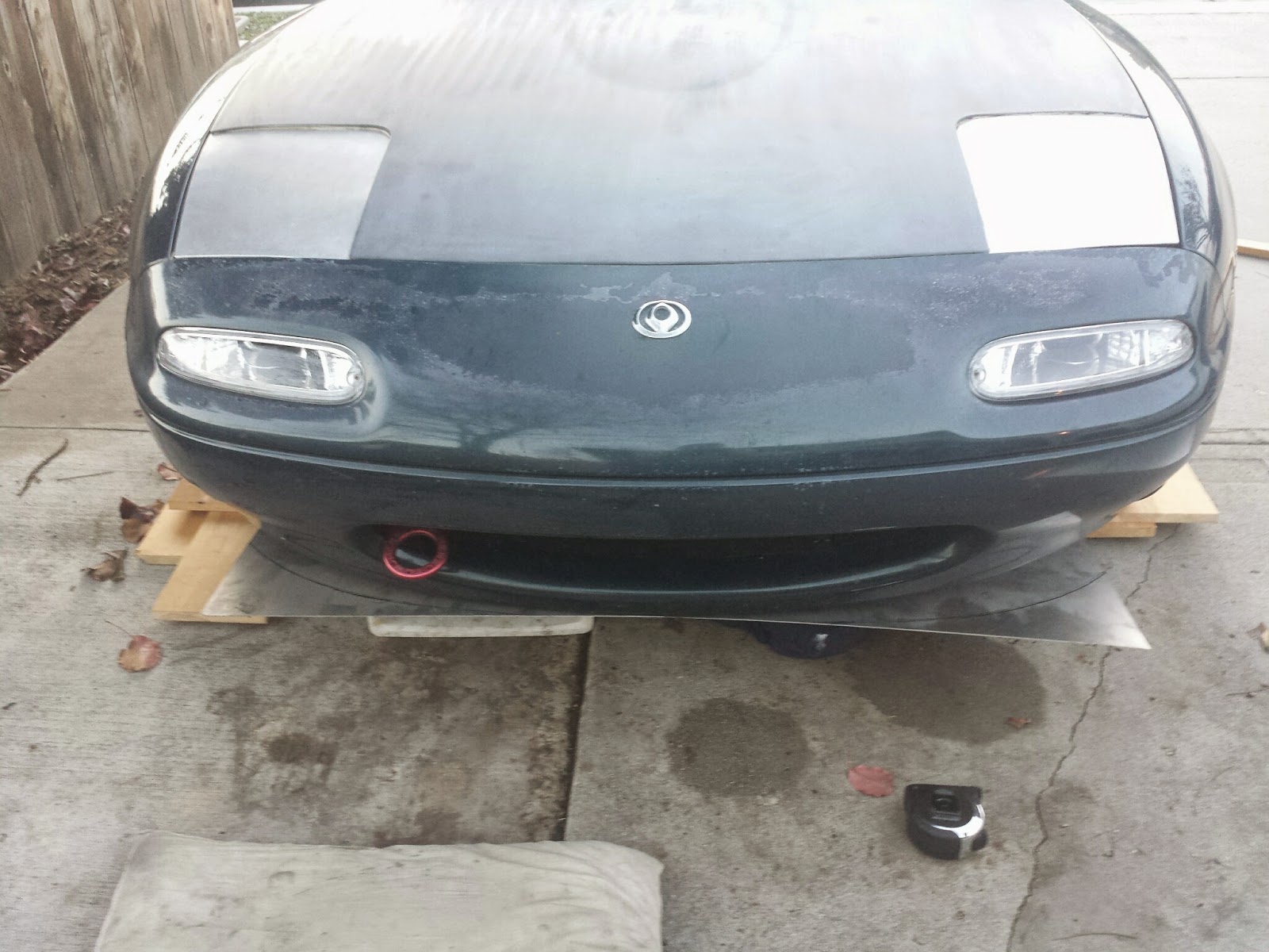
Construction began by jacking up the car, removing the splitter and wedging the first sheet under the front of the car, using whatever was handy.

I traced the curve of the bumper onto the metal and checked it against the splitter.  It looked close enough.  My plan was to sandwich the sheet between the bumper and the splitter.  That would theoretically hold it very snugly and continue to allow the splitter to flex when it scrapes on everything.

I used my reciprocating saw to make the big cuts.  Aviation (tin) snips were used for fine tuning.  I planned to use the splitter to determine where all the front holes should be, but it was too flexible to give me any confidence.

To get a good idea where my holes should go, I needed to be able to put it into place on the car, but I couldn't lift it high enough because it was hitting the front lower control arms, so I made the first rough cutouts for wheel and suspension clearance.

I then put screws facing down through the bumper mounting holes, put the aluminum in place and tapped it with a mallet on each screw.

I marked each dimple to make sure I didn't mistake some random ding for a screw location.

 After drilling, it seemed to line up well, so I did a test fit.  This just might work!

At the end of the first day, I had made a lot of progress, and made a much bigger mess than expected.

One important detail was getting the right hardware to mount everything.  I used my new tap and die set to figure out the size of a captive nut I planned to use.  The threads were in rough shape so I actually got this wrong.  M5x0.8 is definitely different than M6x1.0.  I took my incorrect information to the hardware store and proceeded to spend $50 (!!!) on nuts, bolts and washers.  Be aware, M12x1.25, ultra-fine thread bolts are expensive--$3.68 each, and I got six.  I got everything I could in stainless.

To finish the installation, I had to get the rest of the mounting points done, but they had to be accurate.  First I installed the bolts with which I was going to mount the undertray.  I then screwed the aluminum in place on the bumper, pushed it up against the mounting hardware then wailed (tapped) on the bolts with the dead blow hammer.  This gave me divots exactly where I needed to drill holes.

I drilled my holes and even made a boss for the middle mount with a stack of washers and the dead blow hammer.

One of my mounts was going to use a very beefy chassis brace bolt (the previously mentioned expensive M12x1.25), but it needed some spacers to work properly.  I used a couple thick grade eight washers.  I'm a little nervous about this setup, but I think it should be fine.

Here are a few washers I had to modify due to my  M5 vs. M6 mix-up.  I tried to use the largest possible washers to hold the aluminum.  The goal was to spread the load as much as possible to avoid tearing the sheet metal.

Once everything was ready, I came up with the the genius idea of taping the bolts in place for installation.  I couldn't really think of another way to hold the hardware on both sides of the large sheet.

Here's everything ready to slide under the car.  I just noticed it looks like a giant smiley face.  The mouth is the chassis brace I mentioned.

All the bolts lined up perfectly.  I say it was my fabrication skill, but it was mostly luck.
Now I needed to check if the splitter would bolt on.  It wouldn't.  I did a little trimming and bending; then it fit.

It was now time for finishing touches.
Tire clearance is important.
This is the final shape.  The wings at the back didn't really do anything, and there is nothing to mount them to.

Here's the finished product.  I installed self-drilling screws into the frame rails at the trailing edge.  I might replace them with rivet nuts someday, but they were a good way to do the initial install, since they ensure the holes are aligned.  I will probably add a cutout to make oil changes easier, but that should be simple.
We did a test drive and heard some rattling, but nothing serious.  I might try some sound deadening coating at some point, but it's not urgent.

This view looks very different now.  I was a little concerned with building up a lot of pressure underhood, and some people mentioned retaining excessive heat in the engine compartment, but there is quite a bit of room for air to escape around the suspension and through the wheel wells.  I'm thinking about adding some better flow paths with some hood vents.

For reference, here's the commercially available version of what I made.  It's a little hard to tell, but mine covers significantly more area and cost significantly less.  This one is $236, while the cost of my materials to do the entire length of the car was about $110.